
26BC 6A Slotless Brushless DC Mini Motor Portescap
In the BLDC motor is fed a PWM inverter. Decoding the signals from the Hall effect produces signals from the inverter gates. It is based on the use of 6 different steps according to an angle of 60o electrical rotation. The term trapezoidal refers to the current waveform and the form of the back electromotive force that is produced by this process.
Product Reviews 96V 2000W Brushless DC Motor, 10 Nm, 2000 rpm, 25.7A 96V 2000W Brushless DC
. Figure 1 shows a SIMULINK model of a BLDC motor fed by a six step inverter used for the determination of the moment of inertia of a BLDC motor with load at different load settings..

Brushless dc motor driver cuts board space by 80
The permanent magnet brushless DC motor (BLDCM) is typically controlled using the six-step commutation method, and the flux-weakening method is employed to enable the motor to operate at speeds higher than the base speed. Currently, it is considered that the weak magnetic angle range is 0-pi/3, while the range for deep weakening is pi/3-pi/2.

Brushless DC Motor Fed by SixStep Inverter MATLAB YouTube
Design of buck-type current source inverter fed brushless DC motor drive and its application to position sensorless control with square-wave current. Hung-Chi Chen. A 120° conduction (six-step) method [3-9] and 150° conduction (12-step) method [1, 2] are two commutation schemes for six-switch VSI. Additionally, various VSI.

B0810A1 Autoclavable Slotted Brushless DC Motor for Surgical Hand tools
Description A three-phase motor rated 1 kW, 500 Vdc, 3000 rpm is fed by a six step voltage inverter. The inverter is a MOSFET bridge of the Specialized Power Systems library. A speed regulator is used to control the DC bus voltage. The inverter gates signals are produced by decoding the Hall effect signals of the motor.

15V to 60V ThreePhase Brushless DC Motor PreDriver
A three-phase motor rated at 1 kW, 500 Vdc, and 3000 rpm is driven by a six-step voltage inverter. A MOSFET bridge serves as the inverter. The DC bus voltage is controlled by a speed regulator. The Hall Effect signals from the motor are decoded to create the inverter gates signals.
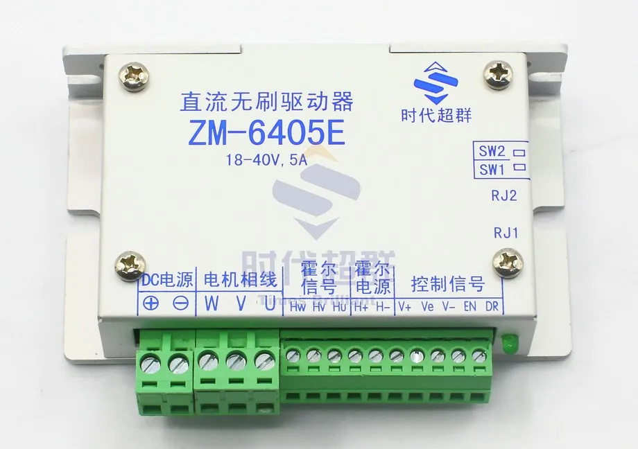
DC brushless driver control ZM 6405E Brushless DC motor below 200Win Electronics Stocks from
. Some researchers have used different optimization techniques for weight reduction or harmonics elimination [34]. Some other researchers have investigated the optimization of the back EMF.

Reduced sensor configuration of brushless DC motor drive using a power factor correction‐based
MATLAB Simulink model of Brushless DC Motor Fed by Six Step Commutation Inverter | Six-Step InverterReach the Electrical engineering Research Experts @ www.m.

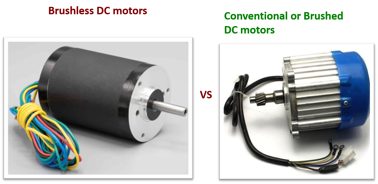
How to Tell if a DC Motor is Brushed or Brushless? Assun Motor
Brushless (BLDC) DC motors find many industrial applications such as process control, robotics, automation, aerospace etc. Wider usage of this system has demanded an optimum position control.

24V Outrunner brushless dc motor 75mm Buy Product on I.CH All rights reserved
The high gain converter is controlled using an outer speed loop and an inner current loop to regulate the DC link voltage of the BLDC with a six-step inverter. A comparative study of the Boost converter-fed brushless DC motor and the high-gain converter-fed BLDC motor is carried out.

Cannulated Microdebrider / Shaver Motor (B0612H1005)
The Six-Step VSI Induction Motor Drive block represents a classical open-loop Volts/Hertz control, six-step or quasi-square wave drive for induction motors. The block obtains the stator supply frequency from the speed reference (neglecting the slip frequency). This frequency is used to compute the stator flux position necessary to generate the.

How to Power and Control Brushless DC Motors DigiKey
Brushless DC Motor Fed by Six-Step Inverter. The use of a Six-Step Switch-on mode for a trapezoidal PMSM motor rated 1kW, 3000 rpm and speed regulated.. The starting of a 5 HP 240V DC motor with a three-step resistance starter. Open Model. Subsyncronous Resonance in Steam Turbine and Governor System. Sub-synchronous resonance (SSR) in Steam.
1.5kW Brushless DC Motor, 4.78Nm Peaco Support
Introduction. The STSW-PTOOL2V1 firmware provides low voltage three-phase brushless DC motor control with the STEVAL-PTOOL2V1 reference design board based on the advanced STSPIN32F0252 BLDC controller with STM32 MCU. The package includes a sample implementation to drive a BLDC motor with Hall sensors position feedback.

MATLAB Simulink model of Brushless DC Motor Fed by Six Step Commutation Inverter SixStep
MATLAB Simulink model of Brushless DC Motor Fed by Six Step Commutation Inverter | Six-Step Inverter#bldcmotor #bldc #electrical #electricalengineering #elec.

Speed Regulation of a Brushless DC Motor Drive Using a Variable DC Link SixStep Inverter
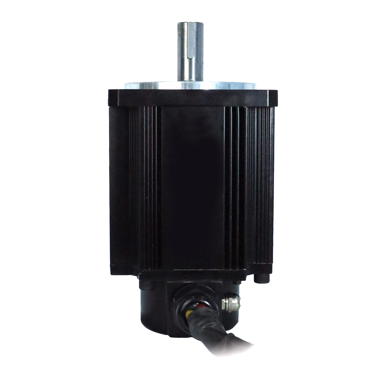
A common "Permanent Magnet Brushless DC" (PM BLDC) motor consists of a 3-phase coil wound on a cylindrical shaped magnetic core (the STATOR) and a rotor/shaft assembly which is normally held in place by bearings which mount at either end of the stator.
Mikro Pendel Religiös dc motor brushed vs brushless Ehrlich rotes Datum Abkürzen
How brushless DC motors differ from brushed DC motors and how they work How BLDC motors can be controlled using six-step commutation (trapezoidal control) The different components of a BLDC motor control algorithm such as PWM control, commutation logic, three-phase inverter and sensor GitHub is where people build software.